How to read house construction plans
Understanding construction drawings or Working Drawings can be difficult for the average person. Most people can easily understand Design Drawings, but working drawings are used by the builder during construction, so they require a great deal more detail as well as a lot of construction jargon.

Working drawings show how the building will be constructed, and how the house will “work” (hence the name). These drawings show information such as exact dimensions, construction notes and references to other professionals details (that are to be read in conjunction with the working drawings).
Working drawings can also show detailed construction information in a much larger scale. These are called “Detailed Drawings” and include wet area details, cabinetry details and bulk head details for example.
Below are typical examples of working drawings that are produced by building designers and architects for use during construction. They have been provided to you in a format that provides an explanation of notes and graphics shown on plans. The plans provided are typical floor plans, a site plan, a sub-floor plan, elevations and a section.
There are two different types of interactive options available to you:
- Magnify – Just hover over the plan and click if you want to see the whole plan up close.
- Interactive floor plan – Click on the ‘interactive floor plan’ button and hover your curser over the shaded areas. Hovering will provide quick information on what that piece of information means. Clicking on the shaded area will update the ‘blue’ information box in the top left hand corner, providing a detailed description.
So let’s get started.
Plan 1: Floor plan
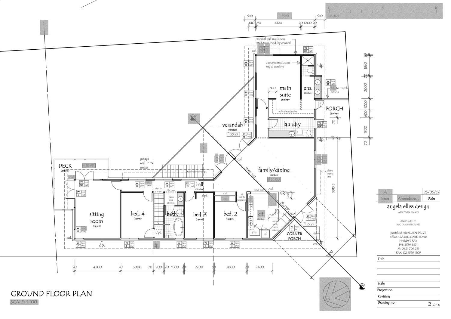
A floor plan is an overhead view of the layout of the spaces inside a dwelling (cut through the walls at 900mm from floor level). The floor plan will include locations of fixtures like sinks, hot water systems, electrical box’s and etc. Floor plans will include general notes specifying finishes and construction methods. Any extra detailed information about finishes and PC items will be included in documents called Specifications or Schedules. These documents hold the information about your home that cannot fit onto the plan. These documents are created by the building designer to ensure that the builder and the client both understand the type and quality of finishes required for the build.
Note: Dimensions are generally shown to indicate room lengths and widths, wall thicknesses as well as ceiling heights and roof heights.
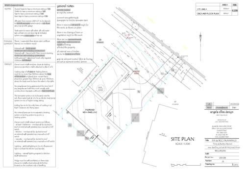
Plan 2: Site plan
The site plan shows the relationship of the new building to the site and how it relates to; services, slope of the land and neighbouring buildings. Site plans should also note the location of underground services, retaining walls, setback requirements, easements, fences, location of driveways and walkways, and sometimes even topographical data that specifies the contours to Australian Height Datum (AHD).
Plan 3: Sub-floor Plan
The sub-floor plan provides details of how this area will be constructed and how services will be arranged. The services will require ‘roughing in’ onsite before the footings are constructed.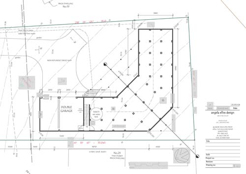
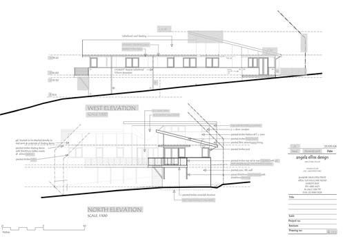
Plan 4: Elevations
Elevations are a 2D view of each external elevation of the house. Plans include front, rear and both side elevations. The elevations specify roof & ridge heights, the finished ground heights of the site, exterior finishes, roof pitches, fence locations and other details that are necessary to give the house its exterior architectural styling.
Plan 5: Section
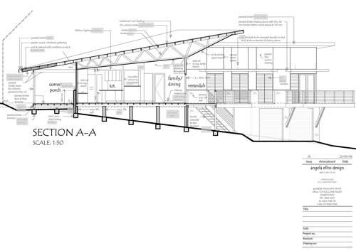
A section is generally cut through a detailed section of the home and is shown as a very dark line with a letter on both ends. It describes how the building will be constructed and describes the internal finishes. Sections explain construction types in more detail.


